

RAL10KIT: STARTER KIT FOR AMATEUR RADIO ASTRONOMY
 You’re an experimenter who loves to build his own equipment, saving money and savoring the satisfaction of working with a tool made with your own hands?If you wish to launch yourself in the exciting challenge of building a microwave radio telescope, if you have a minimum of practice with the electronic construction (you really don’t need much ….) and love to “get your hands dirty” with a soldering iron and electrical wires, the RAL10KIT is the right product for you.It is a module developed “ad hoc” for amateur radio astronomy: is the central core of a Total Power-receiver (common to the whole of RAL10 product family) that integrates the important (and critical) functions of a radiometer and is programmable via software.To build your own radio telescope you need a Satellite TV antenna in Ku-band (10-12 GHz) or C-band (3-4.5 GHz), complete with mechanical supports, illuminator and LNB (Low Noise Block Converter). The signal received by the antenna, amplified and converted in frequency by the LNB (moves down the “receiving window” in the 900-2000 MHz band), is sent to the RAL10KIT receiver via a coaxial cable.You can choose any type of antenna and TV-SAT accessories, new or recycled. The larger the antenna, the more sensitive the telescope.After assembling RAL10KIT in a metal box and realizing a regulated power supply, you can connect the coaxial cable coming from the antenna, install the supplied software on the PC and……we are ready for first observations!
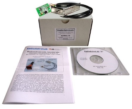
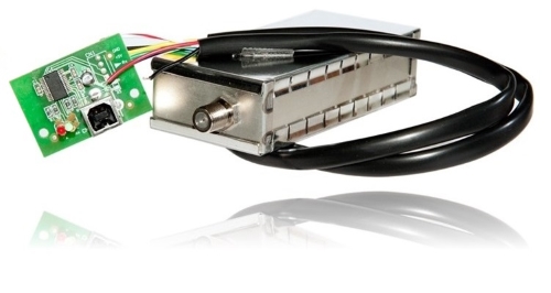
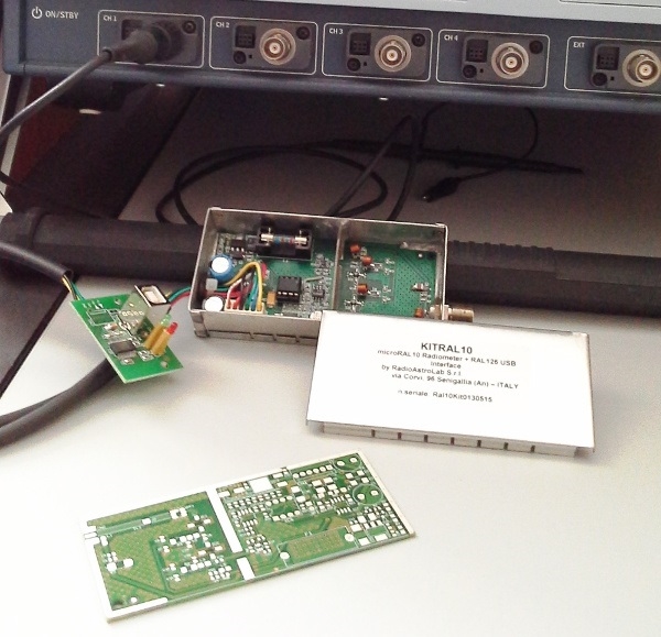
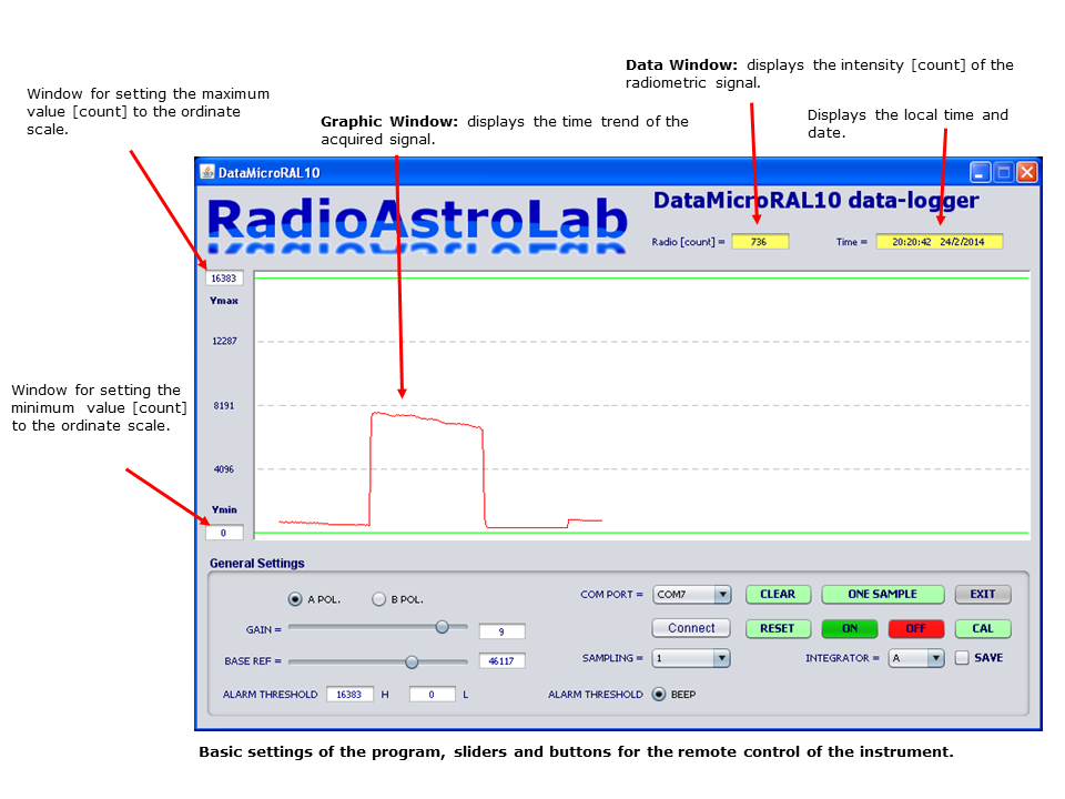
The package includes the radiometric module, the USB interface to connect to the station PC and the software for data acquisition and instrument control.
Detailed instructions are provided for the assembly and installation of the radio telescope: if you have any questions or issues please contact us, we’ll help!
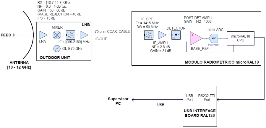
The diagram shows the structure of the instrument: the first two blocks (antenna, LNB and coaxial cable) are commercial components, the rest is RAL10KIT. Although the image indicates a reception band 10-12 GHz (the most common one, given the availability of satellite TV accessories in our area), you can use LNB (and relative antenna) with any input frequency, as long as the output frequencies are included in the reception “window” accepted by RAL10KIT (1390-1440 MHz).
The filter at the input defines the form of bandwidth, and protects against interference, maintaining the possibility to receive the “magic” frequency of the hydrogen at 1420 MHz.
The receiver amplifies and measures the received signal strength and, via an analog-digital converter (ADC) with high resolution, it converts the detected signal into digital form, by positioning the level of “zero” in the appropriate point of the scale. The critical functions of the receiver, as well as the possibility to set various operating parameters and communication with the PC via the USB interface module, are handled by the processor, to the benefit of the economy, compactness and accuracy in the measurement. To optimize the sensitivity of the system, you can integrate the detected signal with a programmable time constant.
The acquisition and control software is always provided for free, usable with all major PC platforms: to our customers we guarantee constant support and free upgrades.
Indeed, the use of a module designed “ad hoc” for the radio astronomical observations ensures safe and repeatable performance, especially for those who approach for the first time to the amateur radio astronomy.
Technical features
- Input centre frequency RF-IF: 1415 MHz.
- Bandwidth: 50 MHz.
- Typical section gain RF-IF: 20 dB.
- Input impedance (F-type connector): 75 Ω.
- Polarization selection (horizontal or vertical).
- Selection of the LNB reception band (LOW BAND – HIGH BAND).
- Temperature compensated quadratic detector (measurement of RF power).
- Setting of the offset for the radiometric baseline.
- Automatic calibration of the radiometric baseline.
- Programmable integration constant (from 0.1 seconds up to 26 seconds).
- Programmable post-detection voltage gain: from 42 to 1008 in 10 steps.
- Acquisition of the radiometric signal with 13-bit ADC.
- Processor that controls the receiving system and manages the serial communication.
- Storage of radiometer parameters (internal non-volatile memory).
- USB interface (type B connector) for connection to PC.
- Compatible with ARIES acquisition and control software.
- Supply voltages: 7 ÷ 12 VDC / 50 mA (Receiver), 20 VDC / 150 mA (LNB).
- Power supply for LNB through coaxial cable, protected with internal fuse.