

RAL10TS: TOTAL-POWER MICROWAVE RECEIVER
RAL10TS is a precise microwave radiometer particularly accurated with regard to sensitivity and the stability of the measurement, as required by the most advanced amateur radio astronomical observations. The wide range of control and operating parameters programming make it the flagship instrument of our line of Total-Power receivers.
A robust metal enclosure houses the electronics of the instrument, controlled through a USB port that connects the RAL10TS to the station PC handled by our software. The receiver sensitivity is ensured by the wide bandwidth (250 MHz) and by a high gain of the pre-detection section, while an automatic control (PID) of the internal temperature of the instrument, which minimizes the variations of the amplification factor and of the parameters operating at different external temperatures, ensures stability and reproducibility in the measurement.

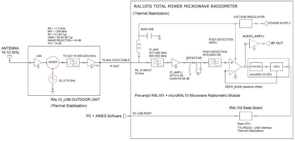
The previous image shows the block diagram of a radio telescope that uses the RAL10TS receiver.
Although a 10-12 GHz reception band is indicated (the most common one, given the availability of the TV-SAT accessories in our area), you can use LNB (and relative antenna) with any input frequency, as long as the output frequencies they are included in the reception “window” accepted by RAL10TS. It is also possible to build a radio telescope that operates directly in the frequency band accepted by our receiver, without using frequency converters (LNB), but a chain of low noise amplifiers and band-pass filters. Of course, taking into account the antenna used, it is necessary to ensure sufficient amplification for a correct detection of the received signal, together with a suitable filtering to minimize interferences.
The radio signal captured by the antenna, amplified and converted in frequency by the external LNB unit (Low Noise Block Converter), is transmitted through a coaxial cable to RAL10TS that measures its power. The level of the detected signal is adapted to the acquisition dynamics of the internal analog-digital converter that converts the analog radiometric information into numerical data suitable for further processing with the station PC.
In a Total-Power radio astronomy receiver, the measure involves the acquisition of small variations in the signal received due to radio source, superimposed on an almost-constant component, of much greater magnitude, introduced by instrumental noise. To evaluate only the “useful” signal you must subtract from the detected signal the contribution due to the background noise: an offset voltage REF_BASELINE is therefore generated, that serves to position the level of the base line radiometric at a suitable point of the acquisition scale.
RAL10TS, run by a couple of microprocessors, processes the detected signal, sets the reference for the base line, the post-detection gain and the constant of integration of the measure, provides for the formation of the serial data packet for the communication with the station computer and stabilizes the internal temperature.
Via the USB serial communication channel you remotely control the instrument.
Connecting the BF-OUT output with a standard stereo audio cable equipped with 3.5 mm mini-jack connectors to the input of the PC sound card, you can perform additional analysis on the post-detection signal: parallel to the basic radiometric observation, you can hear the “noise revealed” or identify potential man-made interference with the help of one of the many free programs available on the web for the analysis in the frequency domain (spectrograms), or programs that display the signal in the domain time as a graphic recorder, widely used by amateurs radio astronomers.
To use RAL10TS where the supply voltage of the electrical network is not available, you simply plug into the socket on the rear panel an external power source to 12 V (rechargeable battery or rechargeable battery unit RAL10BT).
These characteristics classify RAL10TS as an ideal tool to meet any installation need for a semi-professional amateur radio telescope.
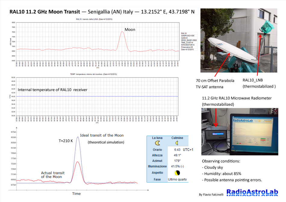
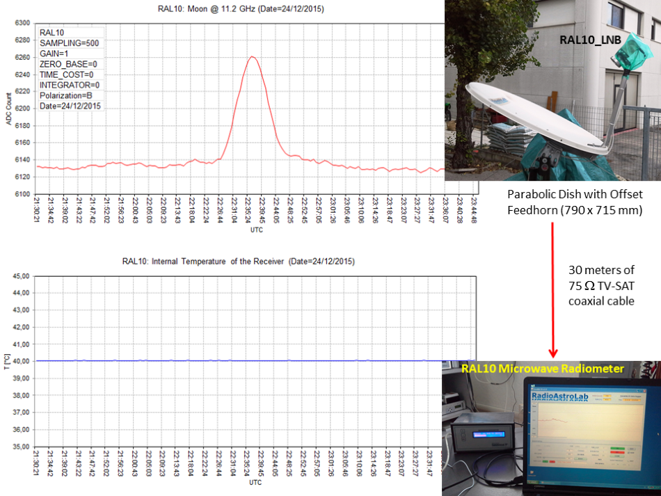
Radiometric recordings of a lunar transit with RAL10TS operating in the band 10-12 GHz. The antenna used is an offset parabolic reflector for TV-SAT with a diameter of about 70 cm, equipped with our RAL10_LNB thermo-stabilized. The first experiment took place on a cloudy, humid day, with the antenna oriented in the expected position of the Moon in the sky at 5:43 UTC on 4 December 2015. For the orientation of the antenna a simple manual system is used: the lack of precision caused pointing errors, resulting in the reduction in the maximum intensity of the signal with respect to the theoretical one (compare the actual recording chart with the ideal of the simulated registration chart). At the time of observation, the percentage of the lunar disc lighting was below 50%. The external unit (RAL10_LNB) is thermally stabilized at 40°C, while the receiver (RAL10TS) is thermally stabilized at 45°C (see the graph showing the internal temperature of the radiometer). In the band 10-12 GHz the Moon radiates like a black body at about 200 K.
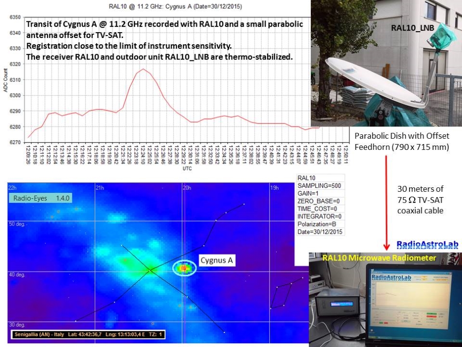
The following image shows a recording of the transit of Cygnus A, close to the detection limit of the radio telescope (due to the small size of the antenna used), registered with the RAL10TS operating in the frequency band 10-12 GHz. Cygnus A is a (elliptical) radio-galaxy far 600 million light years (in Cygnus constellation), one of the most intense radio sources in the sky: however, at the working frequencies of our radio telescope, its emission is at the limit of the instrument’s detection capability (see graph showing the flux density of the most important radio sources in the sky, besides the Sun and the Moon). For a “surer” detection you need to use larger antennas.
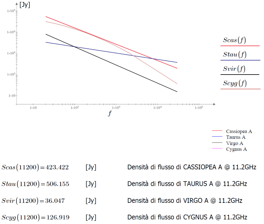
Spectrums and flux density, at the frequency of 11.2 GHz, of the most important radio sources of the sky characterized by a non-thermal type emission mechanism (spectrum with decreasing intensity with increasing frequency).
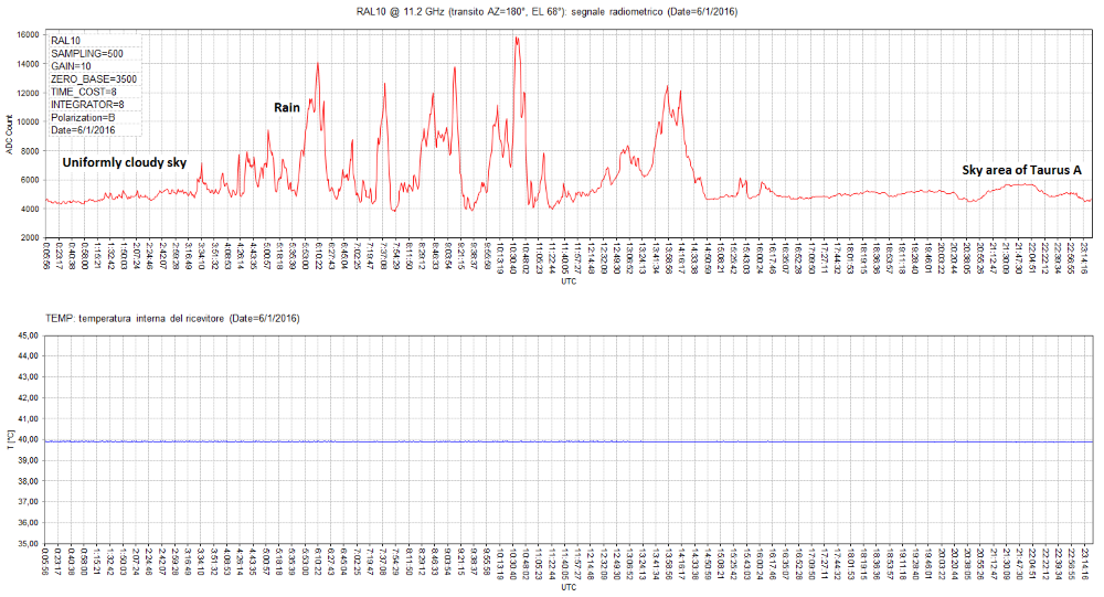
This experiment illustrates the sky scenery “seen” by a radio telescope at 11.2 GHz using the RAL10TS receiver and standard satellite dish for TV-SAT. Despite the stability of the receiving system, it is evident the influence of cloudy sky and rain on the quality of radio astronomy observations in this frequency band: since the emission of the radio source Taurus A is rather weak (a small antenna is used), its transit seems confused and difficult to interpretation because of tropospheric noise caused by weather events.
RAL10TS Technical features
- Dimensions: about [200L, 100H, 155P] mm.
- Weight: about 1.5 kg
- Input Band: 1225 – 1475 MHz (BW = 250 MHz).
- Typical gain of the RF section: 36 dB.
- Input impedance (F-connector): 75 Ω.
- Switching of polarization (horizontal or vertical) with voltage jump.
- Quadratic detector with temperature compensation to the measurement of the RF signal power.
- Setting of the offset for the radiometric baseline.
- Automatic calibration of the radiometric baseline.
- Programmable time constant of the integrator: from about 0.1 seconds to about 113 minutes.
- Programmable gain in post-detection voltage: from 42 to 1008 in 10 steps.
- Acquisition of the radiometric signal with 14-bit ADC.
- Storing of the radiometer operating parameters.
- Nr. 2 microprocessors for system management.
- Post-detection audio output (3.5 mm mini-jack stereo connector) for audio monitoring.
- USB interface (type B) for the connection to the PC with proprietary communication protocol.
- Stabilizing of the internal temperature with PID PWM regulator (about 40°C) and protection for the maximum temperature.
- External power supply: 12 VDC – 2 A min.
- General power supply protected by fuse
- LNB power supply through coaxial cable, protected by fuse (led interruption signal)
- Power supply: Input: Network 85-264 VAC / 47-63 Hz, 36W, 12 VDC via external unit RAL10BT (rechargeable battery).