

RAL10MW: TOTAL-POWER MICROWAVE RECEIVER
RAL10MW is a compact and flexible, high-performance microwave radiometer developed for applications in radio astronomy, environmental remote sensing (passive microwave remote sensing) and atmospheric systems. It can also be used in medical and industrial sectors. Its compactness, operational flexibility, the ability to program and store a complete set of operating parameters and a calibration procedure for the output signal allow its use in a wide range of application sectors.
The structure of the radiometer is conceptually simple: basically, it’s a radio frequency bandpass amplifier followed by a precision detector with quadratic characteristic and wide dynamics that calculates the noise power associated with the received signal, integrated within the bandwidth of the device. The radiometer doesn’t perform frequency conversions and directly detects signals within its bandwidth. The type of antenna used, the specific reception band and its width, the overall radio frequency gain and other characteristic parameters will be established by the external LNB unit, dedicated to the particular application.
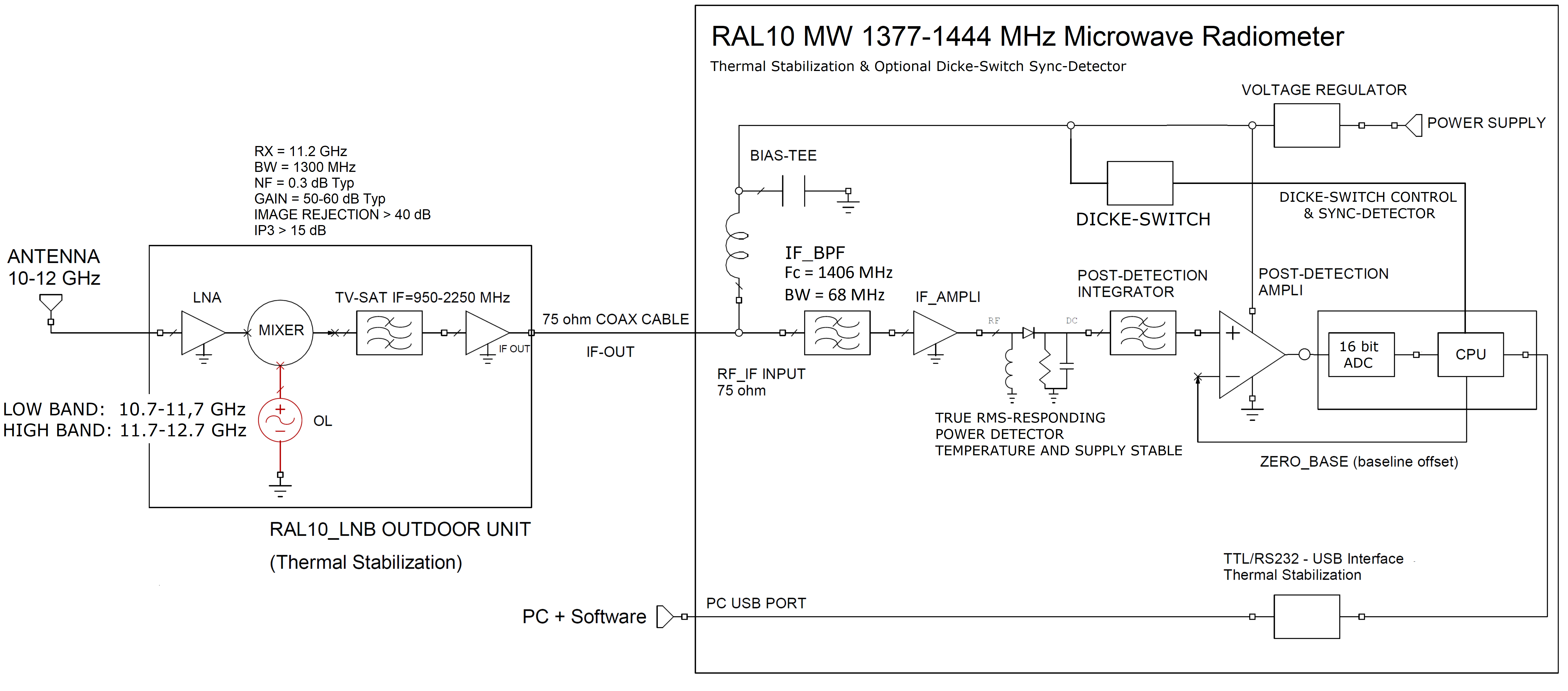
The previous image shows the block diagram of a radio telescope using RAL10MW radiometer.
The block on the left represents a generic LNB outdoor unit, complete with illuminator, assembled on the focal point of a parabolic reflector antenna commonly used for TV-SAT reception. The intermediate frequency signal 950-2250 MHz from the outdoor unit is transmitted to the RAL10MW radiometer through a 75 Ω coaxial cable, amplified and processed by the receiver, transmitted to the station PC through a USB serial port.
To minimize the effects of external interference, it is advantageous to limit the bandwidth of the system around the 1420 MHz frequency, reserved for radio astronomy research.
The program for the station PC, supplied with the radiometer, specific for automatic acquisition and control of the RAL10MW radiometer, is the RAL10MW_DataLogger, a basic and easy to use program.
Please note: After installing the RAL10MW_DataLogger program and creating the shortcut on your computer, in order to stard the program and proceed with the acquisition, you need to run the file as administrator (richt-click on the shortcut and choose the “run as administrator” option).
The program controls all the operating parameters of the instrument, allows you to view the progress of the measurements over time and to store the data in a text format file, easily usable for subsequent processing. The variations of the acquired radiometric data are displayed on the graphics window as moving trace of red color: in a rectangular diagram, the abscissa is the time variable (expressed in UTC time) and the ordinate is the intensity of the signals expressed in relative counting units [count] if the instrument has not been calibrated, or in [K] (equivalent antenna temperature) if the instrument has been calibrated. When the measurement in [count] (counting unit of the analog-digital converter) is selected, the scale varies between 0 and 65535 units (16 bit resolution).
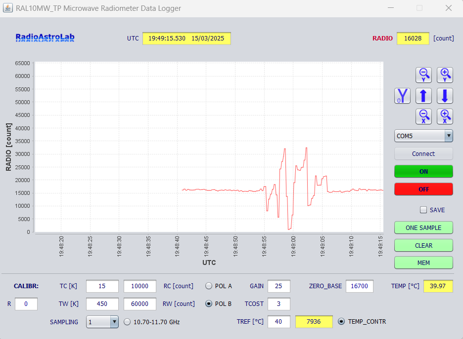
The program is very simple and includes everything needed to manage and display the measurements, with possibilities for setting the graphic scales and programming the operating parameters.
RAL10MW Technical features
- Dimensions: L= 200 mm, H= 100 mm, D= 155 mm.
- Weight: about 1.5 kg.
- Input frequency band: 1377 – 1444 MHz.
- RF input: F-type connector, impedance 75 Ω.
- Precision square detector circuit for measuring RF signal strength.
- Offset setting for radiometric baseline.
- Automatic radiometric baseline calibration and control.
- Programmable post-detection voltage gain.
- Programmable integration constant.
- Storage of the receiver operating parameters in the internal memory.
- Measurement of radiometric signal and internal temperature: ADC 16 bit.
- Selection of the reception band for compatible LNB (tone 22 kHz).
In the standard configuration, the 22 kHz tone for receiving band switching and the selection signal for receiving polarization are sent to the outdoor unit via the coaxial cable.
- Radiometer control with microprocessor.
- Internal temperature control with PID regulator (programmable from 40 to 55 °C).
- Calibration procedure of the measurement scale in equivalent antenna temperature [K] after entering the storable calibration parameters.
- USB serial communication port with proprietary protocol.
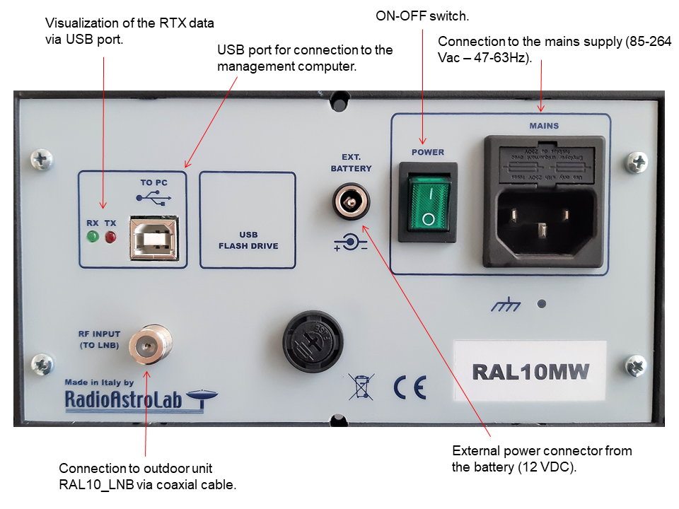
- Power supply: 85-264 VAC / 47-63 Hz, 36W.
- Low voltage supply: 12 Vdc from external source (battery).