

RALMAG FLUXGATE MAGNETOMETER
It is well known that the Earth’s magnetic field, or geomagnetism, is deeply influenced by the Sun: the activity of our star perturbs the electromagnetic environment surrounding the Earth, causing a complex of phenomena that include, for example, magnetic and ionospheric perturbations, polar auroras and variations in the intensity of cosmic radiation. Constant monitoring of geomagnetic fluctuations is, therefore, an excellent indicator of solar activity: for this purpose, the RALMAG 3-axis fluxgate magnetometer has been developed, which, however, finds numerous applications in various scientific and industrial sectors.The direction and intensity of a magnetic field are measured with a magnetometer, an instrument equipped with technologically different sensors based on the needs of sensitivity, accuracy and the need to measure static or variable magnetic fields. The simplest static magnetic field detector is the magnetic compass. The classic induction magnetometer is suitable for the measurement of variable magnetic fields: it uses as a sensor a solenoid that generates a potential difference induced by field variations, amplified and displayed. The most sensitive instruments, suitable for the continuous measurement of the Earth’s magnetic field, are the proton magnetometer and the fluxgate magnetometer. RALMAG uses three orthogonal fluxgate sensors (X, Y, Z) to vectorially measure changes in the Earth’s magnetic field. The potential of fluxgate magnetometers is due to their compactness, ease of use and sensitivity that makes them suitable for capturing minimal fluctuations in the field due, for example, to solar perturbations. Unfortunately, they are just as sensitive to temperature variations: in practical applications it is necessary to isolate the device to minimize the influence of temperature excursions on the response.
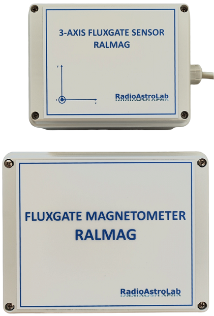
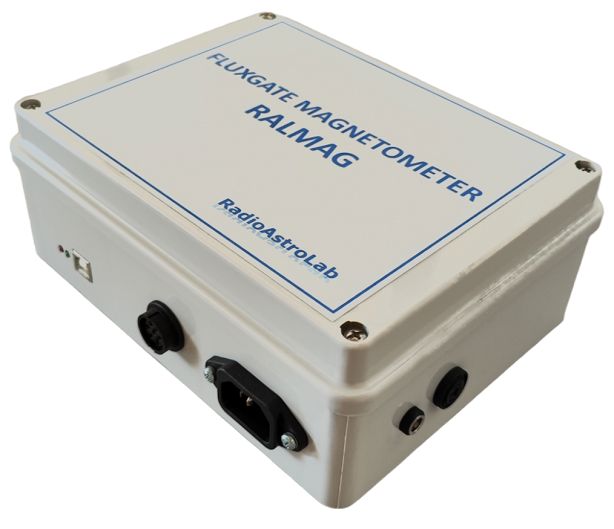
The image shows the RALMAG 3-Axis Fluxgate Magnotemer.
The instrument consists of two units:
-
the sensor module, a watertight box comprising: the 3 orthoganal fluxgate sensors oriented according to the main directions, each sensitive to the respective component of the local magnetic field (X, Y, Z);
-
a temperature sensor that measures the internal temperature of the module.
It is possible to calibrate the system by injecting currents of known value into the solenoid that wraps the sensor of the horizontal component Y through the supplied power supply (following the appropriate procedure indicated in the manual).
The acquisition module including the electronic control circuit of the instrument, the power supply and the USB interface for connection to the management computer. The dataRALMAG software is provided and it controls the instrument, it acquires and saves the measurement values, displays and stores the results as a graph recorder. The tool communicates with a generic external host through a proprietary serial protocol (the protocol details are given in the manual).
The two units are connected by a cable that allows the sensor module installation (the sensor module must be protected and isolated from temperature changes) away from the acquisition circuit in order to optimize its positioning and orientation. For the correct operation of the instrument it is advisable not to exceed 30 meters in cable length.
Fluxgate sensors must be positioned away from potential artificial sources of disturbance (e.g. transformers and electricity distribution lines, vehicles, residential homes…) because frequent current variations could disurb the local magnetic field.
The signals acquired by the fluxgate sensors are processed by the central unit according to selectable sampling periods (1-10 seconds), to be chosen according to the variability of the phenomenon to be observed and the required sensitivity: with identical periodicity, the processor will transmit the measured value to the management computer on the USB serial channel. The high-resolution setting of 10 seconds is great for continuous monitoring of geomagnetic perturbations induced by solar activity.
It is possible to power the magnetometer through a connection to the single-phase mains at 230Vac – 50/60Hz (with dedicated cable), or through a continuous low voltage 12-15Vdc power source (for example external battery) through the appropriate power jack.
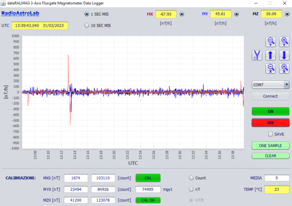
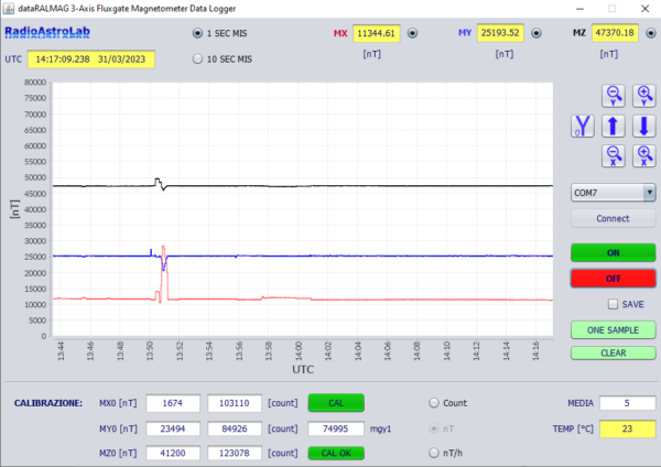
These images refer to the dataRALMAG program developed for instrument control and measurement acquisition.
It is a console where there are commands and a graphic window that shows the trends over time of the magnetic field associated with the three components (red, blue and black traces) and its values in the chosen units of measurement (yellow boxes at the top).
Please note: after installing the dataRALMAG program and creating the shortcut on your computer, in order to start the program and proceed with the acquisition, you need to run the file as administrator (right-click on the shortcut and choose the “run as administrator” option).
After enabling the serial connection between the instrument and the PC (menu with list for choosing the virtual COM port among those available and confirming via the Connect button), when continuous data acquisition is activated (ON-OFF buttons), the tracks move like a graphic recorder from right to left, at the rate of 1 measure per second (when the 1 SEC MIS button is selected at the top) or 1 measure every 10 seconds (button 10 SEC MIS). The scales of the graphs can be adjusted using the appropriate commands.
Using the commands Count, nT, nT/h (bottom), you can choose the unit of measurement (field expressed in uncalibrated units [count] or calibrated [nT]), or the measurement of field variations (in [nT/h]) with respect to the median value, calculated on the number of samples specified in the MEDIA box.
The program displays the internal temperature of the sensor module (in [°C]) and saves the acquired data in a text file, after enabling the SAVE command.
At the bottom, on the console, there are the boxes and commands necessary to enter the calibration data and activate the solenoid that generates a known increase in magnetic field on the Y sensor.
In the first image the measurement of field variations (nT/h) was selected, in the second the standard calibrated measurement (nT) was selected.
The calibration and media parameters are saved in text files (editable) RALMAG_log1.txt and RALMAG_log10.txt (respectively for the sampling mode 1 second or 10 seconds), residing on the folder where the program Data_RALMAG is present.
The following is an example of a text file RALMAG_day_month_year that contains data saved by the DataRALMAG program.
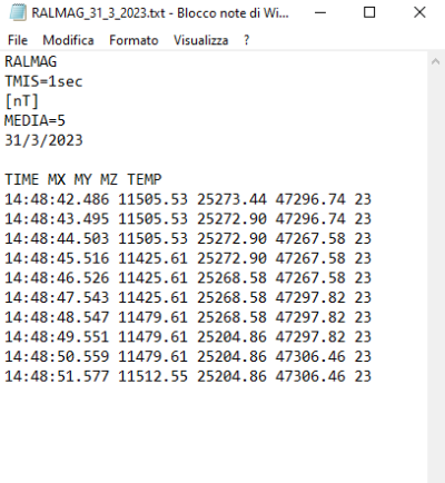
There is a header that shows the values of the selected operating parameters, the start date of the measurement session and the columns of data, separated by spaces, relating to the moments of acquisition of the samples (TIME in hours: minutes: seconds: milliseconds), to the values of the measured field in the three main directions (MX, MY, MZ expressed in the unit of measurement selected and indicated in the header) and to the internal temperature of the sensor module (TEMP) expressed in [°C].
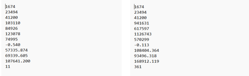
The image is an example of the configuration file RALMAG_log1.txt and RALMAG_log10.txt (respectively for the sampling mode 1 second 0 10 seconds), residing on the folder where the DATA_RALMAG program is present.
The files contain the calibration parameters of the instrument with the following meaning (starting from top to bottom): MX0, MY0, MZ0 (background values of the field in the main directions, in [nT]), mgx, mgy, mgz (uncalibrated values, in [count], corresponding to the responses of the instrument to the respective background values of the field in the main directions), mgy1 (response of the instrument, in [count], to the magnetic field applied during calibration along the Y direction), m (angular coefficient of the calibration line, identical for all fluxgate sensors), qx (known term of the calibration line along the X direction), qy (known term of the calibration line along the Y direction), qz (known term of the calibration line along the Z direction), Nmedia (number of samples used to calculate medians in measuring field variations). All values are editable and are updated at the end of each calibration procedure (see specific paragraph in the manual).
The last parameter Nmedia (must always be an odd number) is entered by the user according to the sampling period chosen and the variability of the phenomenon to be observed (default values: Nmedia = 11 for a 1-second sampling, Nmedia = 361 for a 10-second sampling).
Each time you start the program Data_RALMAG the corresponding configuration files are read, loaded and the calibration parameters are displayed in the appropriate text boxes.
YOU CAN DOWNLOAD DATARALMAG HERE
READ THE MANUAL AND WORK WITH RALMAG:
DATARALMAG REQUESTS THE PRESENCE OF JAVA ON YOUR OPERATING SYSTEM; YOU CAN FIND IT HERE:
Java for Microsoft Windows
Help wiki for the installation and use of Java on Linux OS